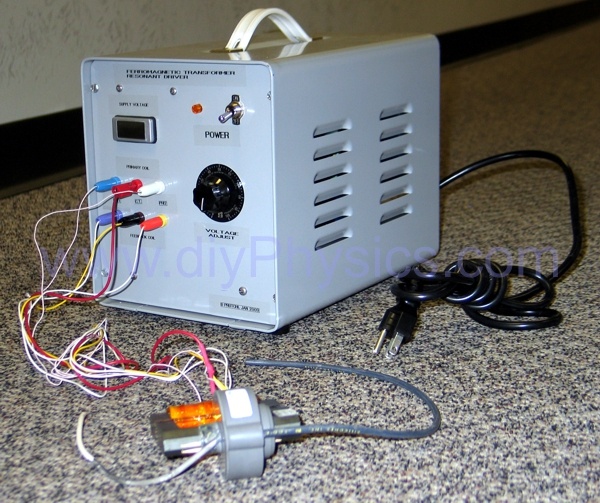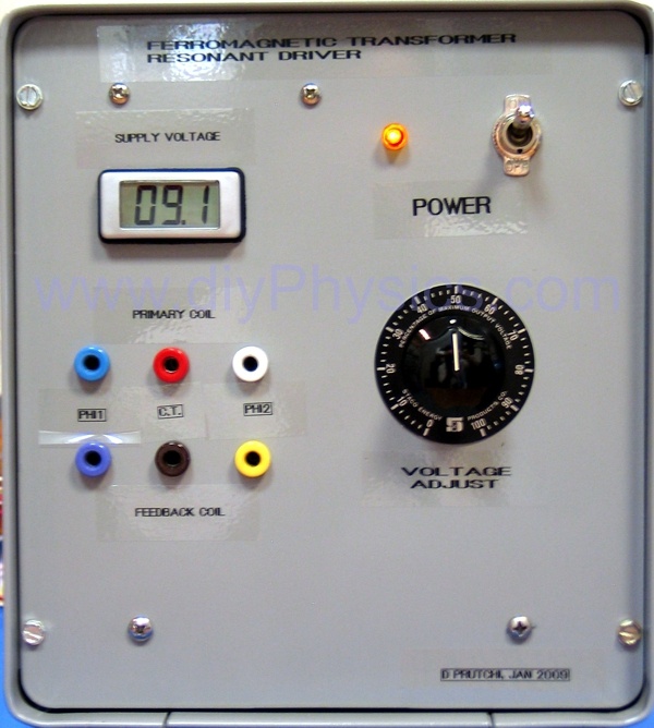
We use the flyback-driver circuit shown in our d.i.y. 250 kV DC power supply in many other of our setups, so we built a stand-alone universal resonant transformer driver. The circuit inside the enclosure comprises a low-voltage, raw-output DC power supply driven from a variac, and the resonant driver circuit shown in the following schematic diagram (click to enlarge):
The low-voltage transformer has a 115 VAC primary and 14 VAC @ 6 A secondary. A 50,000 uF capacitor is used to smooth the output of a CM2502 full-wave-rectifier bridge. A Lascar digital voltmeter measures the voltage of the low-voltage DC power supply.

This instrument drives a resonant transformer in push-pull mode. A feedback coil must be included to make the system oscillate at the transformer’s resonant frequency.


